Table of Contents
Modding the FYGM For Normal Use
In its stock configuration, the FYGM is designed to be connected directly to the Nokia Flexi MultiRadio Base Station via the DIN to HDMI cable. The communication over this cable is a proprietary protocol over RS485 signaling. Since the system it connects to uses this information for timekeeping purposes, we could ostensibly decode the this protocol and do the same in the future.
For the time being, however, it is far easier to simply tap the signal coming out of the LEA-M8T's UART0 and work with it directly, entirely bypassing the 8051 MCU that generates the proprietary protocol. This process involves a bit of fiddling and soldering, but is overall not destructive.
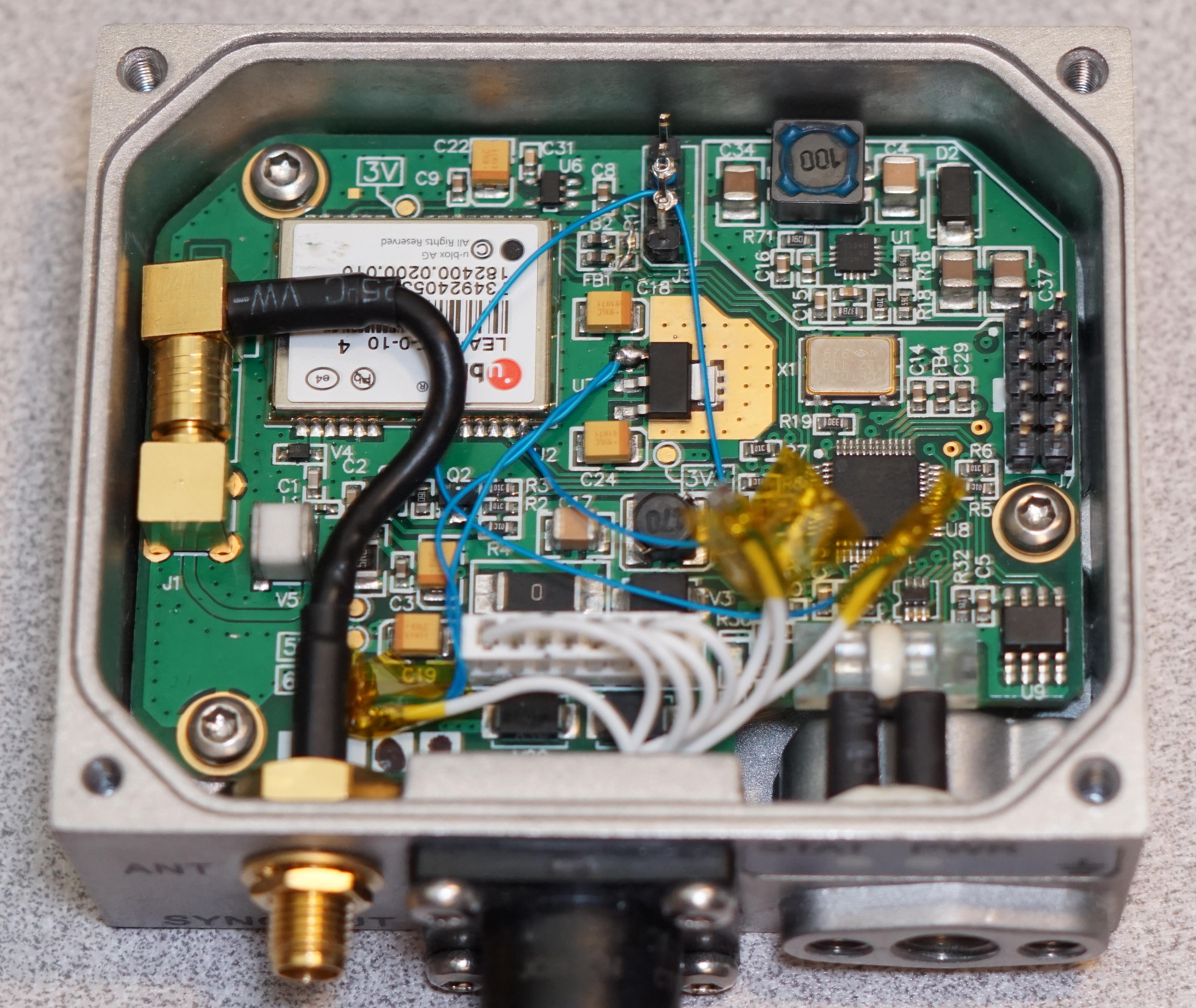
I have two FYGM units, and I have modified both of them in this way. Below are some pictures that can serve as inspiration for someone to do the same, or similar, to their own FYGMs. I used 30AWG sold core wire wrapping wire and found it to work very well for this case. A fine tipped soldering iron and solder are highly recommended.
Overview
Interfacing
The connection between the FYGM and the outside world is managed by a locking DIN connector on the outside and a normal 0.1“/2.54mm removable eight pin header on the inside. You can outright remove the DIN connector and header and run your own cable through the chassis if you're missing the DIN-HDMI cable, but if you have the I would recommend you leave the assembly in place and pull the pins out of the connector.
Pulling the pins is very easy - remove the connector from its socket, then use a device with a very small point (e.g. a pin or fine-tipped tweezers) to slightly lift the plastic catch for the pin you want to pull. Once lifted, you can tug the wire and the pin will slight straight out of the connector. The plastic tabs are easy to break, so if you want to re-use the connector in its stock configuration, be careful not to break them!
The question at this point is - which pins should you pull? The answer depends on how you want to configure it. You need five pins to interface with the outside world: power, ground, Tx, Rx, and PPS.
Ground, pin 6 from the left, should be left in place. The rest I'll go into depth for below.
If you wish to re-use the connector in its stock configuration in the future, you can wrap the data wires around the metal connectors that are crimped to the ends of the wires. That's what I have chosen to do for this unit, wrapping each junction in kapton tape. Soldering and using heat-shrink makes for a more secure, and permanent, bond.
I have not yet documented how the eight pins on this header map out to the DIN connector or HDMI cable - I might eventually, but for the time being I recommend you use your multimeter's continuity testing mode. There are only five pins, and you'll need to do continuity testing on them anyway, so…

Power
Like any piece of complex digital electronics these days, the FYGM needs multiple voltage rails, and as such has multiple DC power supplies on board. The “main” power supply is that which takes 12-30v and through the use of a buck converter, knocks that down to 6.3v. That 6.3v is then fed into a 3.3v linear regulator to power the LEA-M8T and RS485 transceivers, then finally another buck circuit drops it to 1.8v (I believe) for the 8050 MCU. Somewhere along the line, 5-12v is fed to the SMB connector on the board to power the LNA in active GPS antennas - I haven't traced this out so I don't know exactly where it's coming from.
What I have chosen to do is leave the “main” power supply connected via the header, allowing me to drive the FYGM from its design 12-30v. In addition to this, I've done something sneaky.
What I've done is tap off 6.3v from pin 1 of the 3.3v regulator (the part in the center of the board, surrounded by a gold heatsinking ground plane). The idea is that we can use the 6.3v coming from the main supply to power devices attached to the FYGM - a Raspberry Pi, for example. For full disclosure, I don't know how much current is available, but I can say with confidence that I have been able to supply nearly a watt (that is to say, over an amp at 6.3v) to a Raspberry Pi 3 with no problems. I used two 30AWG wires in parallel to increase their current handling capacity, just to be on the safe side. Probably not necessary.
That said, if you choose to do this, configure your Pi with an external power supply that you can monitor (I use one of these and I love it) so you can get a sense of exactly how much power you're going to need. Running a Pi 3 or Pi 4 all out will pull a LOT of power, far more than I would recommend for this use case. However, a Pi running solely as a precision network time source should not pull much power at all (especially if you downclock the CPU for additional frequency stability) and the FYGM's power supply will work perfectly fine.
In the headlining photo of this blog post you can see that I did just that. The silver can attached to the cable is a barrel jack where I can feed in 12-30v. 6.3v is then fed to the Pi through the TimeHat's 5v line, which connects directly to pins 2 and 4 on the Pi. The regulator on the Pi has no problem with 6.3v, I have had the Pi3 in that photo running in this configuration for months with zero problems.

UART Tx/Rx
Graciously, the engineers that designed the FYGM left a header with connecting to the M8T's UART0 easily accessible. This is where we get the NMEA or UBX data in and out of the GPS module. From top to bottom, the pins are GND, Tx, Rx, and 3v3. We only need to tap off the the Tx and Rx pins. By default, the engineers have left a zero ohm jumper resistor off between Rx and the L8T. In order to send data to the M8T, the empty pads at R17 must be shorted - either with a blob of solder or very short length of wire.
The pins on the internal connector you choose to use for Tx/Rx are up to you - any of the six data pins can be used without issue.
On one of my FYGMs, a four pin header was already populated in this spot, so I wire-wrapped directly onto the existing pins. On my other FYGM, the header was not populated, so I soldered to the pads. If your FYGM has pads and no header, and you want do connect to a header - simply solder one in place, it's a very trivial procedure.

PPS
New!
I'm leaving the “old” section, because it may be useful, but microsoldering on the LEA-M8T directly is, as it turns out, not necessary! Instead, leave pin #7 on the white connector in place, it's U3-AY, the positive side of the differential pair of the PPS signal. It perfectly matches the PPS signal coming directly off of the M8T itself.
See this video for more information:
Old
The PPS signal is the trickiest one, because it's not already exposed anywhere easy to get to. What I chose to do is solder a wire directly to the TIMEPULSE pin on the LEA-M8T. Unless you have experience soldering fine-pitch SMT components already, this is a bit tricky. I recommend a bright light and magnifying visor, or a microscope+camera if you're fancy!
Whenever I do soldering like this, I first heat the existing joint and add a small amount of additional solder. I then heat the joint again and apply the connecting wire to the blob, then once it cools, give it a slight tug to make sure it's well attached. 30AWG wire isn't particularly strong in the first place, so don't pull too hard or you'll just break it and have to do it again.
Before you power it up, use a continuity tester to verify that the TIMEPULSE pin is not shorted to its neighbor, EXTINT0. I don't think it would immediately blow up the module if they were shorted, but it could absolutely cause problems or shorten the lifespan of the unit.
If you do bridge the two pins, clean the tip of your iron thoroughly and try swiping it away from the short - alternatively you can try using a very small piece of solder wick to clean it up.

Testing and Wrapping Up
Like any other project, test your setup thoroughly before putting it into production. I have been running my modified units for a few months now with zero problems.
If you do run into any issues, or if you have any suggestions on how to improve this guide, feel free to shoot me an email: [email protected]
Happy GPSing!